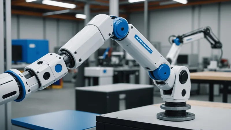
Universal Robots UR5 arms are in a lot of places. That is one of the reasons we built our SDK integration against UR first. If you are deploying EmbodyX at a facility with UR hardware, this walkthrough covers the actual integration steps, what takes time, and where the rough edges are. I will skip the marketing version and just describe what we did.
What You Are Connecting
The EmbodyX SDK sits between the perception layer (camera and the VLA model inference engine) and the arm controller. On a UR5, the arm controller runs PolyScope on the controller box, and external programs communicate with it via RTDE (Real-Time Data Exchange) or URScript commands over TCP/IP. Our SDK uses RTDE for high-frequency state reads (joint positions, TCP pose, safety state) and URScript program injection for motion commands.
The overall data flow: the camera captures a scene frame, inference runs on the edge compute unit and outputs a target TCP pose and gripper command, the SDK translates that pose into a URScript movel command with the configured velocity and acceleration limits, and sends it to the controller. The controller executes the move within its safety envelope. IO signals handle gripper open/close and any task sequencing handshake with upstream conveyors or PLCs.
You do not need to modify the PolyScope installation or write a URCap. The entire integration runs as an external host program communicating through the standard network interface. This is important for facilities with strict controller software change management processes.
Step 1: Network Setup and RTDE Handshake
The UR5 controller needs to be reachable on the local network from the edge compute unit running EmbodyX. Set a static IP on the controller (PolyScope Settings > System > Network). We typically use a dedicated robot cell subnet that is isolated from the facility production network, though the specific network architecture is the facility IT team's decision.
Once the controller is reachable, the SDK RTDE connector verifies the handshake with a sequence/output setup call. The only configuration here is the target IP address and the RTDE port (default 30004). If the controller is running PolyScope 5.x or later, RTDE is available without additional configuration. PolyScope 3.x requires enabling the feature in the network settings panel.
Check: run the connectivity test in the SDK (embodyx check-connection --host <controller-ip>). It should return joint states and TCP pose within 2 seconds. If it times out, verify firewall rules on the network segment. If it returns data but joint positions look wrong, the robot model configuration in the SDK is not matched to your UR5 variant (UR5, UR5e, or CB-series).
Step 2: Camera Mounting and Calibration
Camera placement matters more than people expect on the first installation. The UR5 has a 850mm reach radius. Your camera needs to cover the full task workspace without the arm body occluding the scene during the pick approach. We have found that a fixed overhead mount positioned 600-800mm above the work surface, angled 10-15 degrees from vertical to reduce specular reflections from flat surfaces, covers most UR5 workcell geometries well. If the cell has a defined pick zone that is smaller than the full reach envelope, you can position the camera for that zone specifically.
The critical step is hand-eye calibration: establishing the transformation matrix between the camera coordinate frame and the robot base frame. The SDK includes a calibration procedure that uses a checkerboard pattern and a set of TCP poses you move the arm through manually via the PolyScope teach pendant. The procedure typically takes 20-30 minutes and runs until the reprojection error is below 1.2mm RMSE. If calibration does not converge cleanly, the most common cause is insufficient pose diversity during the data collection: the arm needs to cover a range of orientations, not just translational variation.
Re-run calibration if the camera mount is disturbed or if the arm controller box is moved. Calibration is invalidated by either event. We learned this the hard way when a cleaning crew moved the camera rig 8 centimeters during a shift and the resulting TCP errors caused misplaced parts for two hours before anyone noticed.
Step 3: Safety Envelope Configuration
This step is non-negotiable and takes as long as it takes. Before running any EmbodyX-commanded motion on the live arm, configure the safety planes and joint limits in PolyScope to bound the arm's reachable space to your actual workcell. EmbodyX outputs target poses, and the UR5 controller will attempt to execute any valid pose within its configured envelope. If your safety configuration is too permissive, a bad inference output could command the arm outside the intended task space.
Set safety planes at the physical boundaries of the workcell. Configure tool speed limits appropriate for your application. Run the safety configuration review with the responsible safety engineer at the facility before any autonomous operation. The UR5's integrated safety system handles these constraints at the controller level, not the SDK level. EmbodyX's output is one input to a system that must be safely bounded at the controller level. That is how it should be, and the integration does not attempt to override or shortcut it.
Step 4: Task Configuration and First Run
With connectivity, calibration, and safety configuration done, the task setup in EmbodyX is relatively fast. You define the task in a configuration file: the task prompt describing what the arm should do, the workspace bounds in robot base frame coordinates, the gripper type and IO pin mapping, and the place target for completed picks.
A simple pick-and-place task configuration file is around 30-40 lines of YAML. The task prompt is the most important part to get right. Something like "pick the topmost accessible part from the bin and place it in the output tray" is a good starting point. You will refine it after the first few test cycles based on observed behavior.
First run: load one or two parts into the workcell. Trigger a cycle from the SDK CLI (embodyx run --task pick_place --cycles 5). Watch the arm. The first cycle will likely succeed. Use cycles 2-5 to test with parts in different positions and orientations. If the arm hesitates or the confidence score drops below 0.75 on a cycle, check what the camera was seeing at that moment using the debug frame capture in the SDK. Low confidence usually means the workspace bounds were too restrictive, the part was partially outside the camera field of view, or the lighting changed between calibration and the test run.
What Four Hours Actually Gets You
The "four hours" figure is honest for a standard UR5 installation with a single pick zone, one part type, one place target, and a facility IT team that has already set up the network segment. It includes: 30 minutes network setup, 45 minutes camera mount and calibration, 30 minutes safety envelope configuration (not counting the facility safety review if you need one), 45 minutes task configuration and initial testing, and about 90 minutes of tuning the task prompt and workspace bounds for consistent behavior across the expected part range.
Add time for: facility safety review if one is required, multi-part-type testing, integration with upstream conveyor IO if you need cycle triggering from PLC, and any custom gripper IO that is not a standard two-wire open/close signal. Complex gripper wiring with position feedback can add a couple of hours. PLC IO integration through a ProfiNet or EtherNet/IP bridge adds another hour of configuration if not already present.
The integration is genuinely straightforward for a UR arm with standard connectivity. We are not hiding complexity: what is described above is the actual process. The open questions at most facilities are network and safety policy, not SDK technical complexity. Getting facility IT and safety sign-off on the integration before the integration engineer arrives on site is the single most effective way to compress the total calendar time from first contact to running system.