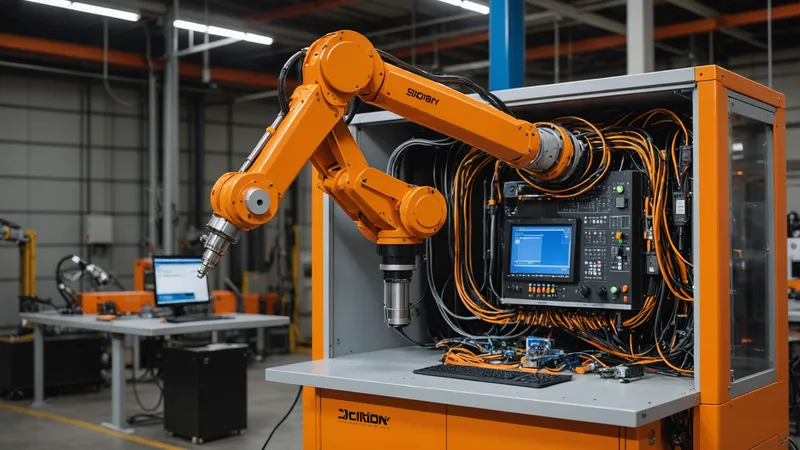
Two Controllers, Two Integration Philosophies
FANUC and KUKA both have substantial installed bases on manufacturing floors worldwide. They are also meaningfully different in how they expose their controller interfaces to external software. Understanding those differences upfront saves several hours of trial and error during integration.
FANUC's R-30iB (and its variants R-30iB Plus, R-30iB Mate) uses a combination of Karel programming, PCIF (PC Interface), and FANUC Robot Server for network communication. The primary path for sending motion commands from an external system is through the PCIF socket connection, which exposes a command/status protocol over TCP. FANUC does not natively speak ROS or URDF; adapters exist, but using them adds a translation layer with its own latency characteristics.
KUKA's KR C4 controller takes a different approach. KSS (KUKA System Software) exposes the RSI (Robot Sensor Interface) and EtherCAT interfaces at a low level, plus the higher-level KUKA.PLC mxAutomation interface for PLC-style command integration. For software integration, the most practical path in recent controller versions is through the KUKA.EthernetKRL option, which allows KRL (KUKA Robot Language) programs to exchange data with external applications over Ethernet via XML structures. The KUKA Sunrise controller, used with collaborative variants like the LBR iiwa, exposes a Java-based API (Sunrise.OS) that is substantially different from the KR C4 path.
EmbodyX's SDK handles both paths through controller-specific connector modules. You do not write connector code yourself; you configure which connector to use and provide the controller's network parameters.
FANUC R-30iB Integration Path
The EmbodyX FANUC connector communicates with the R-30iB via PCIF over a dedicated Ethernet port on the controller cabinet. The factory default for PCIF is port 18735. Before integration, confirm that the PCIF option is enabled on your controller (FANUC charges for this option separately; it may not be active on your cabinet even if the hardware supports it). Check under Menu, then System, then Config, then PCIF on the teach pendant.
Network configuration: the R-30iB and the machine running the EmbodyX edge process need to be on the same subnet with no firewall blocking TCP on the PCIF port. In most factory cell configurations, the controller and the edge compute box are both on a cell-local network segment (typically 192.168.0.x or 10.10.x.x depending on facility conventions). Set the controller's IP address to a static value; FANUC controllers do not handle DHCP reliably in production environments.
In the EmbodyX SDK, the FANUC connector is initialized as follows:
import embodyx
from embodyx.connectors import FanucR30iB

controller = FanucR30iB(
    host="192.168.0.10",
    port=18735,
    robot_model="M-10iA/12",
    tool_frame=1,
    user_frame=2
)
robot = embodyx.Robot(controller=controller)
The tool_frame and user_frame parameters map to the frame numbers defined on the FANUC controller. These must be pre-configured on the teach pendant and match your physical setup. EmbodyX issues motion commands in the user frame's coordinate system; the connector handles the transformation to the controller's joint-space commands.
One FANUC-specific consideration: Karel background tasks interfere with PCIF command processing if they are running continuously at high update rates. If your existing FANUC program runs a Karel task that polls sensors or updates registers at 100 Hz or faster, you may see latency spikes in the command response loop. The EmbodyX connector has a configurable command queue depth and timeout to handle this gracefully, but it is worth auditing your existing Karel tasks before integration.
KUKA KR C4 Integration Path
For KR C4 with KSS 8.x, EmbodyX uses EthernetKRL as the primary communication channel. This requires the KUKA.EthernetKRL software option to be installed on the controller. Check under Help, then Info in WorkVisual, or look for EthernetKRL in the installed technology packages list. As with FANUC's PCIF, this is a paid option that may not be active on your controller.
EthernetKRL uses XML over TCP to exchange data between a KRL program running on the controller and an external application. EmbodyX ships a KRL module (EMBX_BRIDGE.src and EMBX_BRIDGE.dat) that you load onto the controller via WorkVisual. This module handles the XML handshake, receives Cartesian motion targets from EmbodyX, and passes them to the KRL motion instructions. The KRL motion instructions themselves run on the controller. EmbodyX does not bypass KSS motion supervision.
Network setup mirrors the FANUC approach: static IP, dedicated subnet, port unblocked (EthernetKRL default is port 54600). The KR C4 has a dedicated network interface for external communication (not the teach pendant's service LAN); use that interface for EmbodyX communication.
SDK initialization for KR C4:
import embodyx
from embodyx.connectors import KukaKRC4

controller = KukaKRC4(
    host="192.168.1.20",
    ethernetkrl_port=54600,
    robot_model="KR 10 R1100-2",
    base_frame=5,
    tool_frame=3
)
robot = embodyx.Robot(controller=controller)
The KRL bridge module runs in a background task on the controller. Motion commands from EmbodyX are received, validated against the controller's workspace limits, and executed. If a commanded position is outside the controller's software limits, the KRL module rejects it and returns an error to EmbodyX rather than triggering an e-stop. EmbodyX logs these rejections and flags them in the telemetry stream for debugging.
Controller-Agnostic Task Execution
Once the connector is initialized, the EmbodyX task execution interface is identical regardless of which controller you are using. The SDK abstracts the connector entirely from the task layer:
result = robot.execute_task(
    "pick the silver M6 bolt from bin 2 and place it in fixture slot A3",
    scene_camera="overhead_01",
    retry_on_grasp_failure=True,
    max_retries=2
)
print(result.status, result.completion_time_ms)
The VLA model's output is a sequence of Cartesian waypoints and gripper commands. The connector translates these into the native motion commands for the specific controller. Your task scripts do not change when you switch from a FANUC to a KUKA installation.
Common Integration Issues and How to Address Them
Based on integrations we have done at pilot facilities, three issues come up repeatedly.
Frame mismatch: The most common source of positioning errors is a mismatch between the user/base frame defined on the controller and the coordinate frame that EmbodyX uses to output motion targets. Verify frame alignment by commanding the arm to a known reference point and comparing the EmbodyX-reported position against the teach pendant display. Even a small frame origin offset (2-3 mm) will accumulate into visible placement errors over the workspace.
Payload configuration: Both FANUC and KUKA controllers need accurate tool and payload mass/CoG data to calculate accurate motion dynamics. If the gripper + tool assembly mass entered in the controller's payload settings is significantly different from the actual mass, motion quality suffers: the arm may overshoot targets or generate joint torque alarms under load. This is not an EmbodyX issue, but it is one that surfaces immediately when you start running the EmbodyX pipeline and was often masked by slower conventional motion programs.
Speed limits during initial deployment: Both connectors default to a maximum Cartesian velocity of 200 mm/s during the pilot phase. This is intentionally conservative. You can raise it via the max_cartesian_speed parameter once you have validated that the planned trajectories stay clear of obstacles and cell boundaries. Do not raise this limit before running full-envelope validation with the actual cell geometry loaded in the collision model.
What the KUKA Sunrise Path Looks Like (and Why It Is Different)
If you are working with a KUKA LBR iiwa (collaborative arm) on the Sunrise.OS controller, the integration path diverges from the KR C4 guide above. Sunrise uses a Java-based application model, and EmbodyX connects via the Fast Robot Interface (FRI) library over UDP. We have a separate connector for this: KukaSunriseFRI. The FRI path achieves lower command latency than EthernetKRL (FRI can run at up to 1 kHz vs. EthernetKRL's practical 10-50 Hz update rate), which matters for force-controlled assembly tasks. The Sunrise connector is documented in the quickstart guide. This article covers KR C4 specifically because that is where most industrial KUKA deployments in our pilot set sit.